ENCODER_SB
Used to read encoder signal from one or more channels.
Block Screenshot

Contents
Palette
ArduinoDescription
Many sensors (incremental encoder, Hall sensor ...) return a pulses signal for which one wishes to count the edges. The block is used to perform this operation for one or two encoders. It uses the interrupts inputs available on the Arduino board. These inputs are capable of stopping the main program during a change of state (edges of a signal) to execute a subroutine. The subroutine in this case is to increment or decrement a counter.
Pins 2 and 3 are the only pins of the Arduino Uno that support interrupts. On the Mega board, the pins are 2, 3 and from 18 to 21. It is necessary to use an additional signal to determine the direction of the encoder.
Thus, the block offers the possibility to read from a quadrature encoder. It is then necessary that the two channels are wired to the interrupt and the rising and falling edges are taken into account on two channels pins (the precision is increased and can also determine the direction).
On the contrary, if a mode other than the quadrature is used, only one pin must be connected to the interrupt, the other pin can be connected to a conventional digital input.
Do note that the minimum sampling rate is 8 ms for this block.
Dialog box
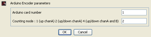
The block has two menus.
The first allows you to select the mode on how to read the signal from the encoder (choice of 1, 2 or 4).
The card number can not be changed at this time.
Mode 1 uses a one interrupt and any digital channel to determine the direction. Only the rising edges of the channel interrupt is taken into account in this mode.
Mode 2 uses the same channels, but both the rising and falling edges of the channel interrupt is taken into account.
Mode 4 corresponds to the quadrature mode. In this mode, the rising and falling edges of the two channels are taken into account.
The second menu allows you to specify the ports used in the mode selected:
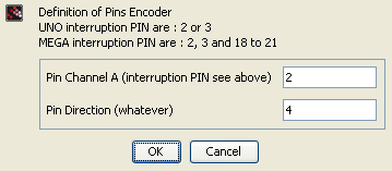
mode 1x : Declaration of interrupt pins 2 or 3 on a UNO card (2, 3 or 18 to 21 for the MEGA board) and a declaration of any digital pin 2 to 13 for a UNO card (2 to 53 MEGA)
mode 2x : Same as above.
mode 4x : Mandatory use of two interrupt pins 2 and 3 on a UNO card. 2 from pin 2, 3 or from 18 to 21 for MEGA.
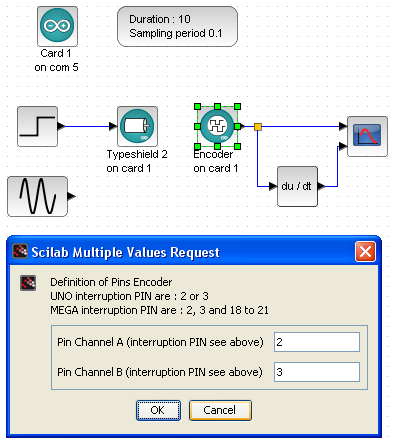
Example 1
The following example shows the use of the block in the case of a motor whose position is noted over time and speed from the signal from the encoder. The 4x mode was chosen to improve the accuracy. The setting of the motor is the same as that of motor example.
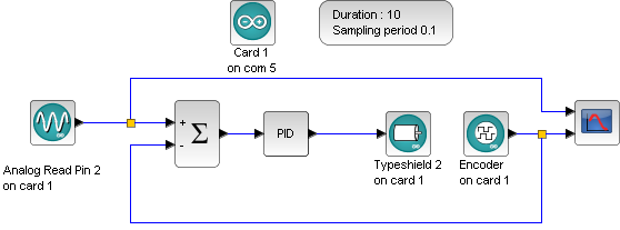
Example 2
The following example shows a position control using information from the encoder for comparison with a reference variable. A PI controller is used to correct the difference and outputting the control voltage for the DC motor.